![]()
KRS-21 PN 16
Uni. Flanged With Tierods
Lateral Expansion Joints are expansion elements designed to absorb lateral movements, created by combining one or two angular expansion joints in a special configuration. These joints effectively control thermal expansion occurring in a plane perpendicular to the axial direction of the pipeline, thereby maintaining the structural integrity of the system.
In lateral expansion joints, the amount of expansion that can be absorbed increases proportionally with the distance between the bellows. This feature offers flexible solutions in system design and allows for customized applications tailored to different expansion requirements.
These types of expansion joints deliver high performance in systems where significant lateral movement occurs. In particular, system designs that incorporate multiple lateral expansion joints offer some of the most effective and safest solutions for absorbing thermal expansion over long distances.
Technical Information
Standard Production: AISI 321 – DIN 1.4541
Custom Production: AISI 304 (DIN 1.4541), AISI 309 (DIN 1.4828), AISI 316 (DIN 1.4401), AISI 316 Ti (DIN 1.4571), etc.
Design Pressure: 16 BAR
Design Temperature: –196 to +550 °C
Standard Flange: Rst 37-2 (DIN 1.0038)
Custom Flange: Stainless Steel according to DIN – BS – EN – ANSI standards, etc.
Standard Hinge: Rst 37-2 (DIN 1.0038)
Custom Hinge: AISI 304 (DIN 1.4541), AISI 309 (DIN 1.4828), AISI 316 (DIN 1.4401), AISI 316 Ti (DIN 1.4571), etc.
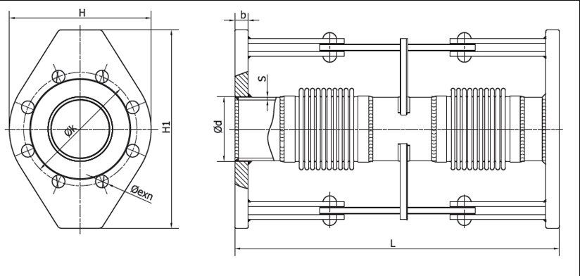
Technical Drawing
Applications
Lateral expansion joints absorb lateral movements that occur in piping systems, thereby reducing stress and vibration-induced noise within the system. They are reliably used in all types of machinery, engines, pumps, industrial process lines, exhaust systems, gas and water pipelines, as well as in potable water applications.
Painting Information
All bellows, hinge, and flange components are coated with a special protective paint against corrosion, regardless of size. This coating ensures long-term durability, especially in systems exposed to outdoor environmental conditions. Surface treatments are meticulously applied in full compliance with quality and safety standards.
Special Note
Design temperatures can be increased up to +950 °C upon request. For special operating conditions, please contact our technical team. For flange dimensions, refer to the “Useful Technical Tables” section. Product weights are subject to a tolerance of ±10%.
| Diameter | Length | Inner | Outer | Tierod Outer Diameter | Lateral Movement +/- | Lateral Spring Rate | Bellows Effective Area | Flange Outer Ø | Flange Center Ø | Flange Thickness | Flange Hole Number | Hole Ø | Approx. Weight |
|---|---|---|---|---|---|---|---|---|---|---|---|---|---|
| 25 | 130 | 36 | 45 | 175 | 12.5 | 38 | 12 | 115 | 85 | 16 | 4 | 14 | 3.8 |
| 32 | 140 | 44 | 53 | 200 | 12.5 | 42 | 18 | 140 | 100 | 16 | 4 | 18 | 4.1 |
| 40 | 150 | 50 | 62 | 210 | 12.5 | 45 | 24 | 150 | 110 | 16 | 4 | 18 | 4.6 |
| 50 | 155 | 61 | 77 | 225 | 10.5 | 46 | 28 | 160 | 125 | 16 | 4 | 18 | 6.5 |
| 65 | 160 | 77 | 97 | 245 | 10.5 | 58 | 35 | 180 | 145 | 18 | 4 | 18 | 8.0 |
| 80 | 170 | 90 | 115 | 270 | 9.5 | 104 | 82 | 220 | 160 | 20 | 8 | 18 | 9.6 |
| 100 | 175 | 117 | 146 | 290 | 9.5 | 131 | 134 | 220 | 180 | 20 | 8 | 18 | 12.1 |
| 125 | 195 | 145 | 170 | 335 | 7.5 | 341 | 192 | 250 | 210 | 22 | 8 | 18 | 15.9 |
| 150 | 225 | 169 | 199 | 375 | 7.5 | 359 | 265 | 250 | 240 | 22 | 8 | 24 | 17.8 |
| 200 | 245 | 220 | 254 | 440 | 7.5 | 371 | 442 | 340 | 295 | 24 | 12 | 22 | 24.5 |
| 250 | 250 | 275 | 315 | 505 | 7.5 | 833 | 683 | 405 | 355 | 26 | 12 | 26 | 35.2 |
| 300 | 280 | 328 | 395 | 570 | 6.5 | 1761 | 1019 | 460 | 410 | 28 | 12 | 30 | 51.2 |
| 350 | 300 | 365 | 419 | 630 | 6.5 | 2259 | 1205 | 520 | 470 | 30 | 16 | 32 | 70.9 |
| 400 | 290 | 410 | 476 | 700 | 6.0 | 3221 | 1538 | 580 | 525 | 32 | 16 | 34 | 94.7 |
| 450 | 300 | 460 | 526 | 760 | 5.5 | 4528 | 1897 | 640 | 585 | 32 | 20 | 36 | 125.5 |
| 500 | 300 | 508 | 569 | 850 | 5 | 5879 | 2273 | 715 | 650 | 34 | 20 | 40 | 156.6 |