![]()
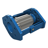
KRS-31 PN 16
Flanged Joint
Angular expansion joints are specially designed expansion elements with flexible movement capabilities, used to control thermal expansion in piping systems. These joints safely absorb expansion in the system by converting axial movement into angular motion in a plane perpendicular to the pipe axis. In doing so, they help preserve the structural integrity of the pipeline and minimize the adverse effects of thermal stresses.
Angular expansion joints are primarily used to accommodate angular movements in a single plane (e.g., perpendicular to the pipeline). However, with special designs, it is also possible to absorb movements occurring in multiple directions. In this regard, they offer flexible solutions tailored to the system’s needs and are suitable for a wide range of applications.
System configurations using two or more angular expansion joints together provide high performance, especially in long-distance pipelines and applications with significant thermal expansion. These combinations make it possible to safely and effectively absorb large amounts of thermal movement.
Additionally, when used in conjunction with fixed points and direction-changing elements, the durability and service life of the system are significantly enhanced.
Technical Information
Standard Production: AISI 321 – DIN 1.4541
Custom Production: AISI 304 (DIN 1.4541), AISI 309 (DIN 1.4828), AISI 316 (DIN 1.4401), AISI 316 Ti (DIN 1.4571), etc.
Design Pressure: 16 BAR
Design Temperature: –196 to +550 °C
Standard Flange: Rst 37-2 (DIN 1.0038)
Custom Flange: Stainless Steel according to DIN – BS – EN – ANSI standards, etc.
Standard Hinge: Rst 37-2 (DIN 1.0038)
Custom Hinge: AISI 304 (DIN 1.4541), AISI 309 (DIN 1.4828), AISI 316 (DIN 1.4401), AISI 316 Ti (DIN 1.4571), etc.
Technical Drawing
Applications
Lateral expansion joints absorb lateral movements in piping systems, reducing stress and vibration-induced noise within the system. They are reliably used in all types of machinery, engines, pumps, industrial process lines, exhaust systems, gas and water installations, as well as in potable water applications.
Painting Information
All bellows, hinge, and flange components are coated with a special protective paint against corrosion in all sizes. This coating ensures long-term durability, especially in systems exposed to outdoor environmental conditions. Surface treatments are meticulously applied in accordance with quality and safety standards.
Special Note
Design temperatures can be increased up to +950 °C upon request. For special operating conditions, please contact our technical team. For flange dimensions, refer to the “Useful Technical Tables” section. Product weights are subject to a tolerance of ±10%.
| Diameter DN Ø |
Length L (mm) |
Welding End Sizes Ø D x s (mm) |
Oval Flange H (mm) |
Angular Movement +/- (°) |
Angular Force (Nm/°) |
Bellow Effective Area (cm²) |
Flange Center to Center (mm) |
Hole Ø (mm) | Flange Hole Quantity | Flange Thickness (mm) |
Approx. Weight (kg) |
|---|---|---|---|---|---|---|---|---|---|---|---|
| 25 | 215 | 33.7×2.6 | 110 | 25 | 0.3 | 24 | 85 | 14 | 4 | 14 | 5.5 |
| 32 | 215 | 42.4×2.6 | 115 | 25 | 0.4 | 27 | 100 | 18 | 4 | 18 | 6.0 |
| 40 | 225 | 48.3×2.6 | 125 | 25 | 0.6 | 30 | 110 | 18 | 4 | 18 | 6.5 |
| 50 | 235 | 60.3×2.9 | 160 | 25 | 0.7 | 33 | 125 | 18 | 4 | 18 | 7.0 |
| 65 | 255 | 76.1×2.9 | 175 | 25 | 0.9 | 48 | 145 | 18 | 8 | 18 | 8.0 |
| 80 | 255 | 88.9×3.2 | 190 | 20 | 1.9 | 74 | 160 | 18 | 8 | 18 | 10.0 |
| 100 | 255 | 114.3×3.6 | 225 | 20 | 2.4 | 110 | 180 | 18 | 8 | 18 | 11.0 |
| 125 | 295 | 139.7×4.0 | 260 | 15 | 4.9 | 153 | 210 | 18 | 8 | 18 | 14.0 |
| 150 | 295 | 168.3×4.5 | 285 | 15 | 8.8 | 231 | 240 | 22 | 8 | 22 | 19.0 |
| 200 | 325 | 219.1×6.3 | 385 | 15 | 12.8 | 412 | 295 | 22 | 12 | 22 | 37.0 |
| 250 | 325 | 273.0×6.3 | 435 | 15 | 23.5 | 610 | 355 | 26 | 12 | 26 | 48.0 |
| 300 | 415 | 323.9×7.1 | 620 | 10 | 71.5 | 978 | 410 | 26 | 12 | 26 | 93.0 |
| 350 | 415 | 355.6×8.0 | 655 | 8 | 86.5 | 1163 | 470 | 26 | 16 | 26 | 127.0 |
| 400 | 415 | 406.4×8.0 | 705 | 8 | 115.0 | 1492 | 525 | 30 | 16 | 30 | 155.0 |
| 450 | 415 | 457.2×10.0 | 755 | 6 | 147 | 1863 | 585 | 30 | 20 | 30 | 170.0 |
| 500 | 415 | 508.0×10.0 | 805 | 6 | 181 | 2269 | 650 | 33 | 20 | 33 | 250.0 |