![]()
KRS-14 30mm
External Pressurised
Externally pressurized expansion joints are a type of axial expansion joint designed to absorb thermal expansion in pipelines along the axial direction. In these types of joints, the bellows are supported by an external casing against internal pressure, ensuring safe performance even in high-pressure systems.
Piping systems are divided into different expansion zones in accordance with engineering principles and isolated from each other through fixed points. Thanks to this structure, the expansion movement occurring in a specific zone is absorbed in a controlled manner solely by the externally pressurized axial expansion joint placed in that zone.
The externally pressurized design allows pressure to be applied to the bellows through a protective casing rather than directly from the external environment. This reduces the risk of buckling on the bellows, extends service life, and ensures high-performance operation of the expansion joint.
This product group is especially preferred for safe use in high-pressure and long pipeline applications.
Technical Information
Standard Production : AISI 321 (DIN 1.4541)
Special Production : AISI 304 (DIN 1.4541), AISI 309 (DIN 1.4828), AISI 316 (DIN 1.4401), AISI 316 ti (DIN 1.4571) etc
Design Pressure : 16 BAR
Design Temperature : – 196 + 550 C
Standard Weldend : Rst 37-2 (DIN 1.0038)
Special Weldend : Stainless Steel etc.
Standard Flange : Rst 37-2 (DIN 1.0038) PN16 – PN25 – PN40
Special Flange : Stainless Steel DIN, BS, EN, ANSI etc.
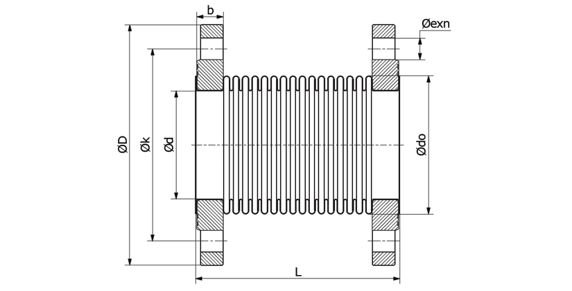
Technical Drawing
Applications
To absorb axial expansions, reduce stress and noise in the system, all machines, all motors, all pumps, industrial applications, exhaust applications, gas and water lines, drinking water lines, etc.
Paint Information
Flanges between DN 25–DN 300 are cadmium plated. For sizes DN 300 and above, specially painted flanges resistant to corrosion are used. It offers high durability and long-lasting use for industrial systems.
Special Note
If requested, the design temperature can be increased to +950°C. Contact us for special requests. Flange tables are in the technical tables section. Product weights have a tolerance of ±10%. Liner is recommended for abrasive fluids.
| Diameter DN Ø |
Length L (mm) |
LF (mm) | L1 (mm) | Outer Diameter Ø Do |
Movement +/- (mm) |
Spring Rate AX (N/mm) |
Bellows Effective Area (cm²) |
Pipe Diameter Ø D x s (mm) |
Approx. Weight (Kg) |
|---|---|---|---|---|---|---|---|---|---|
| 25 | 295 | 305 | 165 | 60,3 x 3,65 | ±5-25 | 19 | 12 | 33,7 x 3,25 | 2,0 |
| 32 | 295 | 305 | 165 | 76,1 x 3,65 | ±5-25 | 20 | 13 | 42,4 x 3,25 | 2,7 |
| 40 | 310 | 320 | 180 | 76,1 x 3,65 | ±5-25 | 21 | 24 | 48,3 x 3,25 | 3,0 |
| 50 | 310 | 320 | 180 | 88,9 x 4,05 | ±5-25 | 22 | 37 | 60,3 x 3,65 | 3,9 |
| 65 | 320 | 330 | 190 | 114,3 x 4,5 | ±5-25 | 23 | 58 | 76,1 x 3,65 | 5,8 |
| 80 | 320 | 330 | 190 | 139,7 x 4,85 | ±5-25 | 24 | 82 | 88,9 x 4,05 | 8,1 |
| 100 | 330 | 340 | 200 | 165,1 x 4,85 | ±5-25 | 37 | 134 | 114,3 x 4,50 | 11,0 |
| 125 | 330 | 340 | 200 | 194 x 5,0 | ±5-25 | 46 | 192 | 139,7 x 4,85 | 14,4 |
| 150 | 340 | 350 | 210 | 219,1 x 6,0 | ±5-25 | 55 | 265 | 165,1 x 4,85 | 17,8 |
| 200 | 370 | 385 | 170 | 280 x 6,0 | ±5-25 | 102 | 442 | 219,1 x 6,30 | 25,9 |
| 250 | 390 | 405 | 190 | 355,6 x 6,0 | ±5-25 | 143 | 683 | 273,0 x 6,30 | 36,9 |
| 300 | 400 | 415 | 200 | 420 x 7,0 | ±5-25 | 155 | 1017 | 323,9 x 7,10 | 51,7 |
| 350 | 400 | 415 | 200 | 455 x 7,0 | ±5-25 | 175 | 1200 | 355,6 x 8,00 | 60,0 |
| 400 | 420 | 435 | 220 | 508 x 8,0 | ±5-25 | 195 | 1533 | 406,4 x 8,00 | 75,8 |
| 450 | 420 | 435 | 220 | 570 x 8,0 | ±5-25 | 253 | 1892 | 457,0 x 8,00 | 85,4 |
| 500 | 450 | 465 | 250 | 615 x 8,0 | ±5-25 | 276 | 2267 | 508,0 x 8,00 | 98,5 |